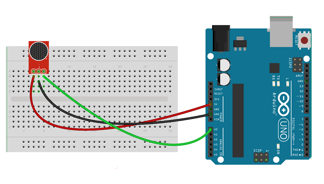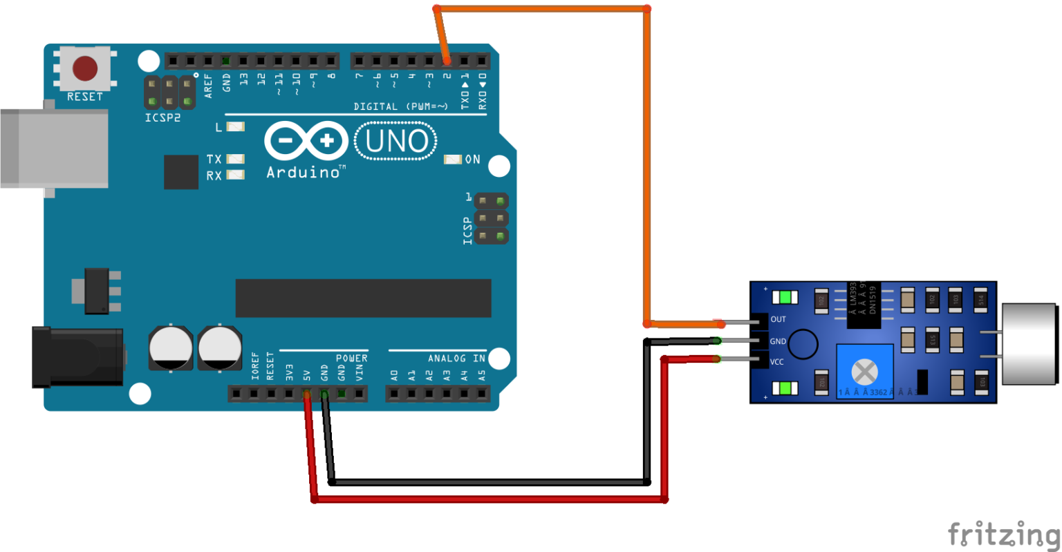

To achieve these two properties we will change a couple of things.įirst, we will configure the ADC to use 3.3V as the analog reference voltage. When sampling sound it is important to take our samples at a constant rate and to take each sample accurately. It was implemented with single sample collection in mind.

The analogRead function of Arduino makes it simple to get a digital value of an analog pin.
SOUND NORMALIZER ARDUINO FREE
Implementing accurate sampling with 3.3V reference and free running Looking at the result you might see that you need to adjust the gain potentiometer such that you utilize the max span for your sound levels while not overdoing it so not to clip your signal. You can then make some sounds at different volume levels and see how your average, min, max and span values respond. Serial.print(", " + String(signalAvg - signalMin)) Serial.print(", " + String(signalMax - signalAvg)) Serial.print(" Span: " + String(signalMax - signalMin)) Serial.print(" Avg: " + String(signalAvg)) Serial.print(" Max: " + String(signalMax))

Serial.print(" Min: " + String(signalMin))

Serial.print("Time: " + String(millis() - t0)) Long signalAvg = 0, signalMax = 0, signalMin = 1024, t0 = millis() determine if analog or digital, determine range and average. measure basic properties of the input signal I have used the following Arduino function to gather data: Look at the board layout and note the main chip so you can identify the device.Īs the first step, I would suggest you take some time to analyze the analog output of your module to see the baseline and amplitude. It is worth noting that a specific design might be on the market under different names as different manufactures make their own versions of the design with their own model numbers. It doesn’t mean that the gain is fixed, it just means that the gain is configurable by you and does not change automatically. To measure sound volume and to be able to compare different measurements one to another you need to use a module where the gain is predictable. Naturally, this isn’t the right choice for measuring sound volume. This will be the right solution for a scenario where you want to record voice for playback or to run a frequency analysis. Such a module will “normalize” the sound to a set level. If your goal is to record sound and get a fixed sound level even in unpredictable situations you will want to get a module with automatic gain like this one based on MAX9814 from Adafruit. I chose to get a module that is available of-the-shelf because it is easier and faster than making your own. You can also make your own module, which has the added advantages of being able to control all the different aspects of the mic and amplification. When choosing a microphone for your Arduino you can get one of the available “microphone modules” that combine a microphone with an amplifier or some other logic on a tiny PCB. Therefore it is important to match the device and the amplification level (gain) to each use-case scenario. On the other hand, a very loud noise and a high-gain amplifier can bring a signal to the max 5V, “over-exposing” or “clipping” it and again bringing us to a situation where the sampling is useless. For this reason a microphone is often used with an amplifier. The ADC needs a 5V/1024=4.8mV change to increase the digital value by 1, but a typical “electret microphone” might not provide this amount of voltage change for quiet sounds. On one hand, a microphone on its own is usually not able to provide enough voltage for the Arduino to sense a change. The Arduino ADC senses voltage levels (typically in the range of 0-5V) and converts them to values in the range of 0 to 1024 (10 bit).ĭepending on what we are measuring, sound levels may be very quiet or very loud. Therefore, for an Arduino implementation, this process translates to connecting a measuring device (microphone for sound) to the MCU and sampling the value at the device by the ADC at a constant rate. Furthermore, each sample in time is also made discrete during this process as computers and integrated circuits have finite accuracy and storage.Īrduino capability for measuring signals and converting them to logic that the micro-controller (MCU) can process is provided by the Analog-to-Digital-Converter (ADC) that is pat of the MCU. Because we can only measure a finite number of times per time unit, this process of measuring is called sampling and it generates a discrete signal. You can think of this as sound passing through a microphone where it is being measured constantly and the measurements form the waveform. Sound is a wave that moves in space and when it is stored (in digital or analog form) it is represented by a Waveform, which is the amplitude of the wave measured at each point in time at a certain point in space.


 0 kommentar(er)
